ToUCam PCVC-740K long-exposure modification
Background Story
Please have a look at the superb pages available all over the globe.
Many thanks to Steve Chambers for sharing his findings with the
internet-community! Please have a look at Steve's page to understand
that it will not be allowed to use the information provided for
purposes of profit.Three pages to be mentioned as being a very good source for rock solid informations:
(1) http://www.pmdo.com/wintro.htm
(2) http://members.bellatlantic.net/~vze29wzh/toucam740mod.htm
(3) http://www.aludobson.de/CCD/umbau_einer_toucam_pro.htm
Please note that whatever you do to your camera is up to you. What I disclose on my pages is based on personal experience. Other setups (OS, software, soldering skills) might lead to other results, don't blame it on me.
Schematics
This is just a tiny little part of it. For convenience I decided to used different NAND gates than shown in (2). Reason being that the ugly style / dead bug / Manhattan method appeared to be the appropriate design choice to me for an incomplex circuit like this one. In dead bug it is easiest to bend pins together... pin 1 and pin 2, pin 3 and pin 12. Half the work done w/o any effort.
Warning
If this is your first SMD-sized project, please do not start directly... do some practice before. A webcam certainly is ruined very very quickly!Photographs...
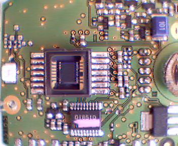
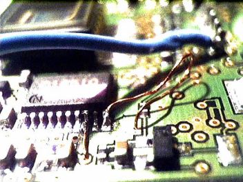
Overview of the battle-field side of the toucam's PCB, cuts already being applied |
 |
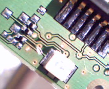
Practice cut.... get rid of additional light produced by the green SMD-LED |
 |
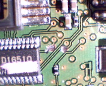
These cuts are essential (see link (2) mentioned above), cutting too much of the mass-plane does not harm, but... watch out for the other leads! I used a sphere type diamond-tool to mill away the leads to be disconnected. |
 |
Wires do not need to go around the PCB in any case. Here are two vias which can be used to solder [Pad8] to pin 1 of the 4011 (lower wire) and [Pad10] to the potential switch (upper wire). I used 0.2mm "magnet wire" (enameled copper wire)... In these places, the wires are soldered to the PCB-vias. BTW: finally I did not add a switch to the cam... what for anyway? |
 |
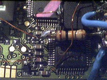
The leads (0.2mm magnet wire) connecting "Pin8" to pin 11 (4011) and [Pin10] to the 100k resistor. Both wires use "foreign" vias to channel to the side of the PCB (as long as the enamel varnish is not scratched at the tunneling portion of the wire, no problem can be encountered). |
 |
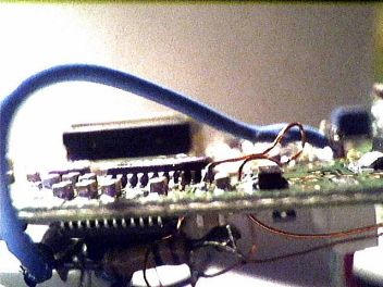
Both sides of the story.... the blue wire is the power supply for the 4011. (Sure, I could have searched for another place to get 5V from.... but, time is money, isn't it?). |
 |
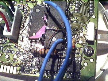
And... on the other side of life.... Dead bug "mounted" (cyan-acrylate) 4011 with 100k resistor. In the upper quarter of this image the connection between [Pad8] and pins 1 and 2 of the 4011 is visible. The lower quarter show the "tunneled" leads to pin 11 (4011) and to the 100k resistor. |
 |
Dead bug 4011.... the two blue wires are the link to the parallel port connector. |
 |
Switch?
You will need the switch only if you intend to take still-image with the camera in the common way. For video the camera will still be working fine with [Pin10] of the 16510 being connected to the 100k resistor.Personally I omitted the switch...
Have a look at an observation using the camera recording the Great Orion Nebula (M42) in combination with an ETX-70.